BlackBerry Bold Touch 9900

RIM's BlackBerry 9900 is the device that the BlackBerry diehards have been hoping, wishing, and waiting for since the original Bold launched way back in 2008.

Apple iPhone 4

Apple iPhone 4 is a touchscreen smartphone developed by Apple Inc. It is the fourth generation iPhone, and successor to the iPhone 3GS.

Samsung Galaxy S II

The Samsung Galaxy S II is a smartphone running under the Android operating system. It is the successor to the Samsung Galaxy S, with a different appearance and significantly improved hardware.

HTC Sensation 4G

The dual-core Android-based HTC Sensation 4G is the latest foray of HTC in Smartphone Market. It's screen is awesome and the camera is top-notch.

Nokia's Smart Move - Nokia N9

After being defeated by Apple and Samsung in the tech war, Nokia is seeking to quietly reestablish itself in the market with its latest smartphone, the Nokia N9.

Lunes, Oktubre 24

Hamster


This lively pet hamster will keep you company throughout the day. Watch him run on his wheel, drink water, and eat the food you feed him by clicking your mouse. Click the center of the wheel to make him get back on it.

Biyernes, Oktubre 14

Energy Isolation

Guide for LO/TO (Lock Out / Tag Out)


Don't be a VICTIM... Don't be a KILLER...


Purpose of Lock Out / Tag Out:
  • To protect workers from the release of hazardous energy
  • To guard against the accidental start-up of equipment during service and maintenance

Distinction must be made between LO/TO and various other locking practices, collectively referred to as Administrative Locking

LO/TO:
Is a specific procedure to ensure Zero-Energy in the system and allow personnel to service, maintain, or modify equipment.

Administrative Locking: 
Normally not used as the primary means of protection during a servicing, maintenance, or modification procedure, and must not be used as a substitute for LO/TO locks or LO/TO tags. It may be performed for many reasons, including equipment security, programmatic purposes, or general safety.

Examples of Administrative Locking are: 
  • Locked fences around high-voltage transformers
  • Locks on overhead-crane disconnect switches
  • A locked door to a laboratory that contains hazardous equipment
  • A water valve locked in the open position

ENERGY SOURCES

Typical sources of energy that may need to be isolated, locked and tagged out include:
  • Electrical: Electric Motors and Batteries
  • Hydraulic: Pressurized Fluids in hoses / pipes
  • Pneumatic: Pressurized Air in hoses / pipes
  • Mechanical: Gravity Systems or Spring Energy
  • Chemical: Storage Vessels or Pipelines containing Toxic / Hazardous Chemicals and Hydrocarbon / Petrol products
  • Thermal: Hot Oil Lines used to heat Heavy Fuel Oil Tanks / Pipe Work
  • Pressurized Liquids/Gases: Hydrocarbons, Petrol and Steam

Note that LO/TO applies to more than just electrical circuits!

Definition of terms in LO/TO:
  • Affected Team Member
    • Refers to the Equipment operator or Equipment owner. Equipment is under repair or servicing being render and LO/TO is being used to isolate energy and prevent operator to operate the equipment.
  • Authorized Team Member
    • A person who locks out or tags out the machines or equipment in order to perform servicing or maintenance on that machine or equipment. Note that an Affected Team Member becomes an Authorized Team Member when that Team Member duties include performing servicing or maintenance covered under this section.
  • Energized
    • Connected to an energy source or containing residual or stored energy.
  • Zero-Energy State
    • A condition that is reached when all energy sources to or within equipment are isolated, blocked, or otherwise relieved, with no possibility of re-accumulation. Equipment is not safe to work on until it is in a zero-energy state.
  • Energy Isolating Device
    • A mechanical device that physically prevents the transmission or release of energy, including but not limited to the following:
      • Manually operated electrical circuit breaker, disconnect switch
      • Manually operated switch by which the conductors of a circuit can be disconnected from all ungrounded supply conductors, and no pole can operate independently
      • Line valve, Block
      • Similar device used to block or isolate energy
      • Push buttons, selector switches and other control circuit type
  • Hot Tap
    • A procedure used in the repair, maintenance and services activities that involves:
      • Welding on a piece of equipment (pipelines, vessels, or tanks) under pressure, in order to install connections or appurtenances
      • It is commonly used to replace or add sections of pipeline without the interruption of service for air, gas, water, steam, and petrochemical distribution systems
      • Termination to energized feeder line
  • Lock Out
    • The placement of lockout device on an energy-isolating device, in accordance with an established procedure, ensuring that the energy-isolating device and the equipment being controlled cannot be operated until the lockout device is removed.
  • Tag Out
    • The placement of a tag-out device on an energy-isolating device, in accordance with an established procedure, to indicate that the energy-isolating device and the equipment being controlled may not be operated until the tag-out device is removed.

Training and Authorization

Only employees who are trained and authorized can perform LO/TO.
  1. Training
    • Equipment operator and maintenance who will perform LO/TO
      • Equipment Safety features
      • Equipment energy supply control system
    • Contractors
      • May be permitted to show written records of equivalent training.
  2. Authorization
    • Manager provides specific authorization after the Team Member satisfies the training requirements
    • Manager must ensure that the Team Member is thoroughly familiar with the equipment and the energy control procedures
    • Manager shall provide additional on-the-job training if the employee is not thoroughly familiar with the equipment and/or written procedure
      • Manager may authorize an employee to perform LO/TO
      • This authorization stipulates the specific equipment or types of equipment on which the authorized employee may perform LO/TO
      • Each manager must maintain records of authorized employees, and the type of on-the-job training
  3. Reauthorization and Retraining
    • LO/TO reauthorization is required when:
      • An authorized employee's job changes or if he/she is reassigned
      • New equipment is to be used
      • New energy-control procedures are to be implemented
    • LO/TO retraining and / or reauthorization is required when:
      • A manager has reason to believe that an employee has inadequate knowledge of LO/TO procedures or policy
      • A periodic inspection shows a deficiency in the authorized employee's ability to implement LO/TO policy correctly
  4. Affected Employee Training
    • Any Team Member may be near to or affected by equipment on which LO/TO is performed
    • All Team Members receive LO/TO awareness training through the New Team Member Health and Safety Orientation and Training course
    • All Team Members must know how to recognize LO/TO, why LO/TO is implemented, and the importance of leaving LO/TO devices in place
    • Team Members are prohibited from tampering with LO/TO devices or attempting to restart equipment to which LO/TO is applied

Lock Out / Tag Out Equipments
Team members who perform LO/TO must be provided with LO/TO equipment and be properly used


  1. Padlocks
    • Padlocks shall be identified as being used for LO/TO:
      • Maybe a red body indicates that it is being used for LOTO
      • Each padlock shall be identified with the authorized Team Member Name, Section & Department
      • Other means of identification (e.g., engraving) are also permissible
    • A manager may appoint to utilize a checkout system that permits authorized Team Member to borrow locks from a common local supply
    • In such cases, the authorized Team Member checking out a lock must re-label it with his / her name
  2. Padlock Labels
    • Each lock must be clearly labeled with the authorized Team Member Name, Section & Department
  3. Keys
    • Each LOTO padlock is required to have two keys:
      • The primary key must be in the possession of the authorized Team Member who applied the lock
      • The emergency key must be kept in a secured area (e.g., a lock box) with access limited to the authorized Team Member immediate manager and one level of management above the authorized Team Member manager
    • A group of locks with a common key may be used for equipment with multiple energy-isolation devices, if desired
      • If a group of locks is keyed alike for this purpose, First key only may be issued for use by the authorized Team Member and the Second key may be kept for emergency use
  4. Tags
    • The tag must always be used in conjunction with a lock unless the energy-isolating device is not physically capable of being locked
    • The tag is required to be attached with a nylon locking cable tie. Protective clear plastic sleeves shall be used for outdoor applications
    • The authorized employee who performs LO/TO must complete all applicable sections of the tag
  5. Other Hardware
    • The manager shall provide other hardware as required such as multiple lock hasps and circuit breaker and valve lockout devices

LO/TO General Procedure

  1. Preparation and Notification
    • Use written procedures:
      • Authorized Team Member must determine if an Equipment-Specific Written Procedure is applicable to the task
      • Authorized Team Member must obtain and follow the equipment- specific written procedure
      • If a new written procedure must be generated, the authorized Team Member must contact his / her manager / supervisor
    • Assess energy type and magnitude
      • Authorized Team Member must assess the type, magnitude, and hazards of the energy to be controlled
    • Determine methods of control
      • Authorized Team Member must determine the appropriate methods of controlling the hazardous energy (e.g. disconnect switch or valve)
      • Note that push buttons, selector switches, interlock circuits, and other control type devices are not energy-isolating devices
    • Notify all affected personnel
      • Authorized Team Member must notify all affected employees of the impending shutdown and the reasons for it
  2. Shutdown
    • Verify that it is safe to shut down equipment
      • The authorized Team Member must verify that it is safe to shut down the equipment
    • Perform normal equipment shutdown
      • The authorized employee must turn off or shut down the equipment using established methods for that equipment
    • Isolate and lock out energy sources
      • Authorized Team Member must operate the energy-isolating device and install LO/TO device
      • The lock must be affixed so as to hold the energy- isolating device in an off or safe position that physically prohibits normal operation of the energy- isolating device
    • Write required information on tag
      • The authorized TM must complete all appropriate information on the tag
      • Tags should not obstruct indicator lights or controls, tag may be located as close as is safely possible to the device, in a position that will be immediately obvious to anyone attempting to operate the device
    • Release stored energy
      • In the case of stored mechanical energy, vent valves, spring releases, blocking devices, or equipment repositioning (as appropriate) must be utilized. In the case of approved grounding wires or discharge devices must be used
      • Verify re-accumulation of energy
  3. Verification of LO/TO Application Procedure
    • Attempt to restart the equipment
      • Authorized Team Member must physically attempt to operate the energy-isolating device and attempt to restart the equipment using the normal equipment controls (e.g., start buttons or computer software controls)
    • If the equipment is electrical, test for zero energy state
      • Authorized Team Member must test potential electrical energy sources using appropriate instruments or testers
      • Authorized Team Member shall also determine if any energized condition exists as a result of inadvertently induced voltage or unrelated voltage back-feed even though specific parts of the circuit have been de-energized and presumed to be safe
      • Only qualified Team Member can executing the energy testing
  4. Release from LO/TO: Before LO/TO devices are removed and energy is restored to the equipment, the authorized Team Member must follow the procedures below:
    • Verify that it is safe to re-energize
      • Authorized Team Member must verify that the work for which the LO/TO was applied has been completed and that it is safe to reenergize equipment
    • Clear all tools and personnel
      • Authorized Team Member must check the work area to ensure that all tools and personnel are at a safe distance from the equipment
    • Remove all isolating and grounding devices
      • Authorized employee must remove any devices applied
    • Replace safety guards
      • Authorized employee must check the equipment to ensure that any removed guards are reinstalled
    • Remove lock and tag, reset the energy-isolating device, and return the machinery to service
    • Notify all affected personnel
      • Authorized employee must notify all affected employees that the equipment is back in service
  5. Temporary Removal of LO/TO Devices
    • When LO/TO devices must be temporarily removed from the energy-isolating device so that the equipment or component can be energized for testing or positioning, the following sequence of actions must be taken:
      • Notify the affected employees and area manager
      • Clear the equipment of tools and materials
      • Remove Team Member from the machine or equipment area and ensure that required tools are safely and properly positioned
      • Remove all repositioned and blocking devices, return all vents and valves to their normal operating positions
      • Remove all grounding / shorting conductors
      • Energize and proceed with testing or positioning
      • De-energize all systems and reapply lockout / tag-out measures to continue the servicing, maintenance, or modification of the equipment. The original tag may be reused
  6. Emergency Removal of LO/TO Devices
    • When the authorized Team Member who applied a LO/TO device is not available to remove, the manager may remove the device. This is considered to be an emergency procedure, to be undertaken only in extreme circumstances. Extreme care must be taken and the following steps must be performed:
      • The manager must verify that the authorized Team Member is not at the facility
        • If the Team Member location cannot be determined, no further action shall be taken
      • The manager must make every reasonable effort to contact the authorized employee
        • This may include a telephone call to the employee's home or other location
      • If the TM is contacted, the manager must inform the Team Member that LO/TO devices will be removed
      • The manager must verify that it is safe to remove the LO/TO devices
      • The manager may then use the emergency key to remove the LO/TO devices, or the lock may be cut off if the key is not available
      • The manager must ensure that the authorized Team Member is presented with the removed lock immediately upon returning to work, and is informed of the reasons for the emergency removal
      • The emergency procedure must be duly recorded in the department's lock out / tag out records and signed by both the manager and the authorized Team Member

Procedure / Application of Group LO/TO

Install Group LO/TO Procedure
  1. The manager must determine that group LO/TO is appropriate
  2. The manager must convene a meeting of all members of the group to be covered under the procedure
    • The manager must describe the tasks to be performed
    • The manager must delegate primary responsibility to a designated authorized Team Member for a specified group of employees working under the protection of the group's LO/TO
    • The structure of the group, the names of all group members and the designated authorized Team Member, and reasons for the group LO/TO must be documented in an appropriate LO/TO logbook
    • Each member of the specified group must be trained and authorized
  3. The designated authorized employee is responsible for ensuring that each step of the general or equipment-specific written procedure is completed
  4. The designated authorized Team Member must apply his/her personal LO/TO lock(s) and tag(s) to the energy-control device(s) and indicate on the tag that a "group lockout" is in effect
  5. The designated authorized Team Member must communicate to each Team member that LO/TO is in place and work may commence
    • Designated authorized Team Member must inform any new group member that a group lockout is in place and communicate to all the information relating to the group lockout
    • The names of the team members must be added to the log
    • Anyone leaving the group before the servicing, maintenance, or modification is completed must notify the designated authorized Team Member
Releases of Group LO/TO
  1. When the work is completed, the designated authorized Team Member must communicate to each group member that the group LO/TO is being considered for removal and:
    • Must verify with each member that all tasks performed in conjunction with the specific job are complete
    • Must verify that the equipment has been returned to a safe restart condition
  2. After positive verification is received from all crew members, the designated authorized Team Member may remove the group LO/TO devices and perform equipment restart
    • If any group member is not present to provide the verification that is required under Steps 1 and 2, the designated authorized Team Member must follow all the procedures as outlined
  3. The designated authorized employee is responsible for making all appropriate logbook entries

Locks and Tags are normally installed in the following order:
  1. Operator Lock
  2. Electrician Lock
  3. Maintenance Lock
Locks and Tags are normally removed in the following order:
  1. Maintenance Lock
  2. Electrician Lock
  3. Operator Lock

Recordkeeping Requirements

Each LO/TO event must be fully documented in the department log, project log, or a dedicated LO/TO logbook

The following information must be documented: 
  1. Name of authorized Team Member who performed LO/TO
  2. Date and time LO/TO was applied
  3. Equipment and circuit identification
  4. Reason for LO/TO
  5. Schematic drawing or print numbers, when available
  6. Date and time of LO/TO removal
  7. Name of authorized Team Member who removed LO/TO if different from authorized Team Member who initiated LO/TO
At the discretion of the manager, recordkeeping requirements may be satisfied by an orderly system of archiving completed tags. Records shall be maintained for two years

An equipment-specific written procedure is required if the equipment undergoing servicing, modification, or maintenance meets one or more of the following conditions:

  1. Has more than one energy source
  2. Requires the operation of more than one device to isolate the hazardous energy
  3. Has potential for stored, residual, or accumulated hazardous energy
  4. Is incapable of being locked out, and a second means of isolation is not possible
At least annually the manager / supervisor of an organization implementing LO/TO shall perform an inspection of the energy-control procedures. The inspection shall be conducted to identify and correct any deviations or deficiencies.

The inspection shall also document the following:
  1. Identification of the machines or equipment on which the energy-control procedure was utilized
  2. Date of the inspection
  3. Names of employees included in the inspection
  4. Name of the person who performed the inspection


Miyerkules, Oktubre 12

Early Detection System

Thermographic Inspection and Ultrasound Inspection

What is Thermography?

Camera capture and converts the infrared radiation into a state that is visible to us. That is how we can see and measure the heat.

Emissivity or Emittance:

The intensity of the emitted radiation depends on two factors, the temperature of the object and the ability of the object to radiate

What makes Thermography so unique and useful?


Thermography provides us with a powerful tool for non-contact temperature measurement, usually surface temperature measurement. But we also need a basic understanding of how the surface is being heated and what might lie behind that temperature.

Why Thermal Scanning?


  1. Safe to use in high voltage, environmental & mechanical hazards
    • Non-contact measurement
    • Long distance measurement
    • Passive sensing is harmless
    • Thermal pattern is qualitative
    • Temperature measurement is quantitative
    • Non-destructive test (NDT)
  2. Cost saving for energy
    • Energy loss is avoided by early detection of faulty equipments
    • No shutdown required for inspection
  3. Cost saving for maintenance
    • Low repair costs due to early diagnosis of the problems
    • Equipment life is extended by pinpointing faulty components before costly damage


Ultrasound Inspection
  • Hear what can not be seen
  • See what can not be heard
  • Low heard through sound conducting obstacles
  • Detectable in high noise environment 
  • Distance from the power source
  • On line monitoring


Tracking, Arcing or Corona?

  1. Tracking
    • No heat, buzzing sound
    • Starts, gradually builds to crescendo, stops
  2. Arcing
    • Heat and buzzing sound
    • Abrupt start and stop, random
  3. Corona
    • Constant buzzing or sizzling sound
    • No heat detected on low voltage systems
Arcing detected with ultrasound on right hand 13.8 kV switchgear.

Ultrasound Inspection Methods - Outdoor
  • Scan 360 degree area
  • Back and forth
  • Up and down
  • Scan same object from different points
  • Parabolic
  • Use headset or loudspeaker

Ultrasound Inspection Methods - Indoor
  • Back and forth
  • Up and down
  • Scan closed panels 
  • Magnetic flexible wand on panels
  • Switchgear is quiet
  • Above dB micro V (SDT 170) should be investigated
  • Always use headset

Combine Ultrasound and Thermography  for more thorough inspections! 

Guide for Electrical Testing and Inspection

Electrical Maintenance Program and Principle of Electrical Testing

Electrical Maintenance Activities Fall into three General Categories:

I. ROUTINE MAINTENANCE
  • Activities that are conducted while equipment and system are in service. These activities are predictable and can be scheduled, staffed and budgeted. Generally this are schedule on a time –based, run time meter or number of operation schedule.

Examples: 
  1. Visual Inspection 
  2. Infrared Scans
  3. Cleaning
  4. Functionality Test
  5. Lubrication
  6. Oil Test
  7. Governor and Excitation System Alignment

II. MAINTENANCE TEST
  • Activities that involved the use of electrical test equipment to determine electrical equipment RELIABILITY in an offline state.

Examples: 
  1. Insulation Resistance Test
  2. Breaker Trip Testing
  3. Alternating Current High Potential Test
  4. High Voltage Direct Current Ramp Test
  5. Battery Load Test

III. DIAGNOSTIC TESTING
  • Activities that involve use of test equipment to access condition of equipment after unusual event such as faults, fire or equipment failure/repair/replacement or when equipment deteriorate is suspected.

Examples:
  1. Turns Ratio
  2. Core Ground Test
  3. Insulation Resistance Test
  4. Insulation Power Test
  5. Winding or Contact Resistance Test

DIFFERENT KINDS OF IDENTIFICATION OF ELECTRICAL HAZARDS

1. Insulation Resistance Test
  • Resistance (in megohms) offered by the insulation to an impressed direct voltage. Insulation Resistance is NOT a definite measure of the voltage an insulation will stand, its is an indicator of the suitability of the insulation for continued service.

Application of Insulation Test Method


2. Dielectric Absorption
  • The time resistance test is independent of equipment size and temperature. It compares the absorption characteristics of contaminated insulation with the absorption characteristic of a good insulation. The test voltage should be applied over a 10 minute period with the data recorded every 10 seconds for the first minute there after. The interpretation of the of the slope of the plotted graph will determine the condition of the insulation. A continuous increase in resistance in the graph indicates a GOOD Insulation. A flat or downward curve indicates cracked or contaminated insulation. 

3. Polarization Index
  • The steepness of the dielectric absorption curve taken at a given temperature indicates the relative dryness of the insulation.

Polarization Index = R10 / R1 = The value must be more than 1.

where:
R10 = MegaOhms at 10 minute reading
R1 = MegaOhms at 1 minute reading

NETA STANDARD / IEEE 43-2000:
Polarization Index should be higher than 1


4. Insulation Power Factor Test
  • The purpose of this test is to determine the state of dryness of the winding and insulation system and to determine the power factor for overall insulation, including bushing, oil and winding. It’s a measure of the ratio of power losses to the volt amperes applied during the test. The power factor obtained is measure of watt lost in the transformer insulation system including the bushing. 

The Power Factor should not exceed 0.5% at 20 degrees Celsius


5. Winding Resistance Test or Contact Resistance Test
  • This is to check the loose connections and broken strands. The most accurate method is to allow the transformer sit de-energized until temperatures are equalized. Take the reading from the top of each bushing to neutral for wye and across each pair of bushing for delta. Result are compared to other phase in wye connection or between pairs of terminal on delta connected winding to determine if a resistance is too high. Resistance can also be compared to the original factory measurement. Investigate and deviate from adjacent pole or similar equipment / devise by more of 25% of lowest value.


6. Transformer Turn Ratio Testing
  • TTR detects shorted turns which indicates insulation failures by determining if the correct turns ratio exist. Shorted turns may result from short circuit or dielectric (insulation ) failure. Measures are made by applying a known low voltage across one winding and measure the induce voltage on the corresponding winding. The voltage ratio obtained by the test is compared to the nameplate voltage ratio. The ratio obtained from the field test should agree with factory data, within 0.5%. New transformer of good quality normally within 0.1%.

Electrical Safe Working Environment


An electrically safe work condition will be achieved and verified by the following process:

  1. Determine all possible sources of electrical supply to the specific equipment. Check application up date drawings, diagram and identification tags.
  2. After properly interrupting the load current, open the disconnecting devices for each source.
  3. Where it is possible, visually verify that all blades of the disconnecting devices are fully open or that draw-out type circuit breakers are withdrawn to the fully disconnected position.
  4. Apply lockout/tag-out, devices in accordance with a documented and established policy.
  5. Use adequate rated voltage detector to test each conductor or circuit part to verify they are de-energized. Before and after each test, determine the voltage detector is operating satisfactorily.
  6. Where the possibility of induce voltages or stored electrical energy exists, ground the phase conductors or circuit parts before touching them. Where it could be reasonably anticipated that the conductors or circuit parts being de-energized could contact other exposed energized conductor or circuit parts, apply ground connecting devices rated for the available fault duty.

Five Behavioral Approaches will Improve Safe Work Places

  1. Determine the nature and extent of hazards before starting a job.
  2. Each employee should be satisfied that conditions are safe before beginning work on any job or any part of a job.
  3. All employees should be thoroughly familiar with and should consistently use the work procedures and the safety equipment required for the performance of the job at hand.
  4. While working, each employee should consider the effects of each step and do nothing that might endanger themselves or others.
  5. Each employee should be thoroughly familiar with emergency procedures.

Electrical Emergency Response

When an electrical accident occurs, due to effect of muscle clamping, a victim is often incapable of moving or releasing the electrical conductor. Attempts to rescue an accident victim may pose as a great hazard for the rescuer as it does for the victim. Caution should be a primary consideration during any electrical accident or emergency. There should be an emergency response plan for scheduled electrical maintenance or work.

A worker with an electrical injury may have any of these signs and symptoms.

ELECTRICAL RESCUE TECHNIQUES

Approaching the Accident
  •  Never rush into an accident situation
  • Call qualified personnel as soon as possible
  • Get the aid of trained electrical personnel if possible
  • Approach the accident scene cautiously

Examining the Scene
  • Visually examine victim to determine if they are in contact with energized conductors
  • Metal surface, object near the victim or the earth itself may be energized
  • You may become a victim if you touch an energized victim or conductive surface
  • Do not touch the victim or conductive surface while they are energized
  • De-energized electrical circuit

Hazards and Solutions
  • Be alert for hazard such as stored energy, heated surfaces and fire
  • If you can’t de-energized the power source use EXTREME care
  • Ensure that your hands and feet are dry
  • Wear protective equipment such as low voltage gloves and overshoes if available
  • Stand on a clean dry surface
  • Use non-conductive material to remove a victim from the conduct

High Voltage Rescue
  • Special training is required for rescues if high voltage is present
  • Protective equipment such as high voltage gloves and overshoes must be worn
  • Special insulated tools should be used
  • Insulated tools, with high voltage rating, are a lifesaver
  • Use devices such as hot sticks or shotgun sticks to remove a victim from energized conductors
  • In some cases, non-conductive rope or cord may be used to remove a victim from a conductor

Rescuing the Victim
  • Stand on the dry rubber blanket or other insulating material if possible
  • Do not touch the victim or conductive material near the victim until the power is off
  • Once power is off, examine the victim to determine if they should be moved
  • Give “First Aid”

First Aid
  • A victim may require Cardio-Pulmonary Resuscitation (CPR)
  • If the victim is breathing and has a heartbeat, give first aid for injuries and teat for shock
  • Ensure the victim gets medical care as soon as possible
  • Provide medical personnel with information on voltage level, shock duration & entry/exit points
  • The treating / attending physical must determine whether the victim should be sent to a “Trauma or Burn Center”

OSHA Regulation

Two very important basic point set by OSHA:
  1. LIVE PARTS shall be de-energized before working on or near them.
  2. Even if the exposed parts have been de-energized, they shall be treated as energized until they are locked out and / or tagged out.

All electrical circuit conductors, bare or insulated, are assumed to be energized until proven otherwise. They shall be de-energized locked out and tested for the absence of voltage before working on them or working near them. Work on the electrical circuit conductors amy only be performed by qualified personnel who have been authorized to do the work.

Electrical Hazards

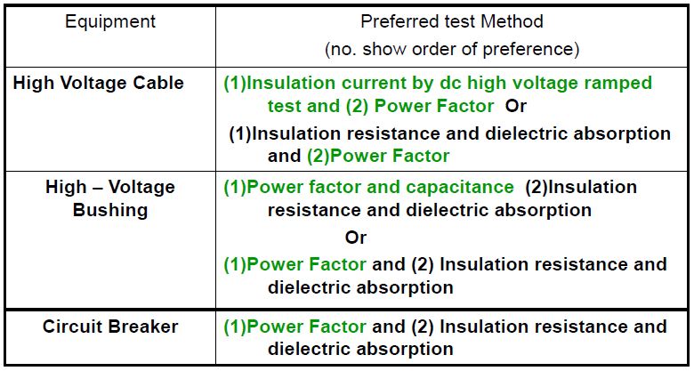
Current is the killing factor of Electricity

Three Categories of Electrical Hazard


ELECTRICAL SHOCK

To some people low voltage means low hazard. Actually, low voltage does not necessary means low hazard, because potential difference is only a factor making up dangerous effect of electricity. The terms high voltage and low voltage are relative terms. The term low voltage is really deceiving. The extent of injury from electrical shock depends on these factors:

• The amount of current conducted through the body
• The path of the current through the body
• The length of time a person is subjected to current


The amount of the current depends on the potential difference and resistance. The effect of low current on the human body ranges from temporary mild tingling sensation to death. An electrical shock can injure you in either or both of the following:

• A severe electrical shock can stop the heart, the breathing muscles or both
• Heating effect of the current can cause severe burns, especially at point where the electricity enters and leaves the body

Effect of Electric Current on the Human Body


Current is the KILLING factor in electrical shock. Voltage is only important because it determines how much current will flow through a given body resistance.


Nominal Resistance Values for Various Parts of the Human Body


Human Resistance


Electrical Shock can happen in Three Ways


1. A person may come in contact with both conductors in a circuit
2. A person may provide a path between an ungrounded conductor and the ground
3. A person may provide a path between the ground and a conducting material that is in contact with an ungrounded conductor

Effects of Electric Shock

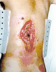
Entrance Wound - High resistance of skin transforms electrical energy into heat, which produces burns around the entrance point (dark spot in center of wound). This man was lucky, the current narrowly missed his spinal cord.

Involuntary Muscle Contraction - This worker fell and grabbed a power line to catch himself. The resulting electric shock mummified his first two fingers, which had to be removed. The acute angle of the wrist was caused by burning of the tendons, which contracted, drawing the hand with them.

Internal Injuries - This worker was shocked by a tool he was holding. The entrance wound and thermal burns from the overheated tool are apparent.

Thermal Contact Burns - Current exited this man at his knees, catching his clothing on fire and burning his upper leg.

Potential Difference


Equipment Grounding

Ground - A conducting connection, whether intentional or accidental, between an electrical circuit or equipment and the earth, or to some conducting body that serves in place of the earth.

Step and Touch Potential

1. Step Potential

    
• Current flow on the surface of the ground for some distance around the point where the earth become energized.
• Step potential is caused by the flow of fault current through the earth. The person closer to the ground rod or grounded device, the greater the concentration of the current and higher the voltage.
• The current flow creates a voltage drop as it flows through the earth’s surface and a person standing with their feet apart bridges a portion of this drop thus creating a parallel path for the current flows as shown the illustration.
• The wider apart a person’s legs are, the larger the voltage difference across the body. Protection from the step potential hazard is to stay in the zone of equipotential while working. Being alert to this hazard is the best defense. This means that person standing near the point where fault current enters the earth may have a large potential difference from foot-to-foot.
• The potential difference over the same span will less and less as the span is move away from either fault current entry point or the fault return point at the source.
• The voltage drops as you move away from the point of contact. If one part of your body touches a high voltage zone while another part of your body touches a low voltage zone, you will be come a conductor for electricity.
• This is why you should shuffle away from the line, keeping your feet close together as illustrated.
To escape from the potential step hazard: feet shuffle away from the line or keep your feet close and have a short hops.

2. Touch Potential


Touch Potential is a problem similar to step potential. It involves a fault current flow in the earth establish a  potential difference between the earth contact point and some nearby conductor structure or hardware. 


ELECTRICAL BURNS

Burns caused by electric current are almost always third-degree because the burning occurs from the inside of the body. It means that the growth centers are destroyed. Electric-current burns can be especially severe when they involve vital internal organs.

Current Duration

The amount of energy delivered to the body is directly proportional to the length of time that the current flows; consequently, the degree of trauma is also directly proportional to the duration of the current. Three examples illustrate this concept:

1. Current flow through body tissues delivers energy in the form of heat. The magnitude of energy may be approximated by J = I 2Rt Where: J = energy, joules , I = current, amperes , R = resistance of the current path through the body, ohms , t = time of current flow, seconds If sufficient heat is delivered, tissue burning and/or organ shutdown can occur. Note that the amount of heat that is delivered is directly proportional to the duration of the current (t).

2. Some portion of the externally caused current flow will tend to follow the current paths used by the body’s central nervous system. Since the external current is much larger than the normal current flow, damage can occur to the nervous system. Note that nervous system damage can be fatal even with relatively Short durations of current; however, increased duration heightens the chance that damage will occur.

3. Generally, a longer duration of current through the heart is more likely to cause ventricular fibrillation. Fibrillation seems to occur when the externally applied electric field overlaps with the body’s cardiac cycle. The likelihood of this event increases with time.

Two Basic Types of Electricity

I. STATIC ELECTRICITY

Static Electricity is an accumulation of electrical charges on the surface of a material, usually an insulator or non-conductor of electricity. There is no current flowing as there is in alternating current (AC) or direct current (DC) electricity. Static Electricity is simply electricity that is standing still - voltage potential with no electron flow.

Typically, two materials are involved in static electricity:

1. It has excess electrons or negative (−) charges on its surface
2. It also has excess positive (+) electrical charges
If one of the materials is an electrical conductor that is grounded, its charges will drain off immediately, leaving the other material still charged.

Static Electricity Sparks

An Electrostatic Discharge (ESD) or sudden flow of electric current across an air gap, heating the air to a high temperature, causing it to glow. The size of the spark depends on the separation of the sources of electrical charges and their potential difference in voltage.

Static and Environmental Condition

Dry Air:
Static electricity is formed much better when the air is dry or the humidity is low. When the air is humid, water molecules can collect on the surface of various materials. This can prevent the buildup of electrical charges.

Rainstorms:
When there is extreme turbulence among water drops, such as in a thunderstorm cloud, static electricity charges can build up on the water drops. Static electricity in created in a thunderstorm cloud.

Static Electricity Shocks

A static electric spark will jump from one material to another when the difference in the amount of positive (+) and negative (−) charges is sufficient to cause electrons to overcome the resistance of the air gap between the two materials.
The electrons heat the air for a fraction of a second, causing the spark and zapping sound.

Applications of Static Electricity

1. Pollution Control:
Factories use static electricity to reduce pollution coming from their smokestacks. They give the smoke an electric charge. When it passes by electrodes of the opposite charge, most of the smoke particles cling to the electrodes. This keeps the pollution from going out into the atmosphere.
2. Air Fresheners:
These devices strip electrons from smoke molecules, dust particles, and pollen in the air, just as what happens in creating static electricity
3. Xerography:
One version of this device electrically charges ink so that it will stick to the paper in the designated areas. Another version of a photocopier uses charges to stick the ink to a drum, which then transfers it to the paper.
4. Painting:
Put charge on the paint material and material to be painted, then spray a fine mist of paint into the material. The charged paint particles are attracted and stick on the painted material.

Risk with Static Electricity

1. Damages electronics parts
2. Trigger gas / fuel / dust explosion

Grounding Prevents Shocks and Sparks

Drain the electrostatic charge to ground, using a grounding wire.

Reduce Static Risk / Hazard

1. Increase Humidity
Static electricity is more active when the air and materials are dry. The humidity is normally lower in the winter, and heating the house further reduces the humidity.
2. Moisturize Skin
Some people have very dry skin that may cause the buildup of static charges, especially in the winter. One thing to try is to use moisturizers or lotions on your skin.
3. Clothes
Some clothing materials, such as polyester materials, cause more static electricity than others when they rub against your skin. Wear 100% cotton or wool clothing.


II. DYNAMIC ELECTRICITY

Dynamic Electricity is electricity that is in motion - voltage potential with electron flow.

Two types of Dynamic Electricity exist:

1. Direct Current
Direct current (DC) is the unidirectional flow of electric charge. Direct current is produced by such sources as batteries, thermocouples, solar cells, and commutator-type electric machines of the dynamo type. Direct current may flow in a conductor such as a wire, but can also flow through semiconductors, insulators, or even through a vacuum as in electron or ion beams. A term formerly used for direct current was galvanic current.

Electrons are flowing only in one direction.
2. Alternating Current
AC is the form in which electric power is delivered to businesses and residences. The usual waveform of an AC power circuit is a sine wave. In certain applications, different waveforms are used, such as triangular or square waves. Audio and radio signals carried on electrical wires are also examples of alternating current. In these applications, an important goal is often the recovery of information encoded (or modulated) onto the AC signal.

Electrons flow alternately in both directions.

AC electricity alternates back-and-forth in direction 50 or 60 times per second, according to the electrical system in the country. This is called the frequency and is designated as either 50 Hertz (50Hz) or 60 Hertz (60Hz).

Advantages of AC Electricity

The major advantage that AC electricity has over DC electricity is that AC voltages can be readily transformed to higher or lower voltage levels for distribution. Changing voltages is done by the use of a transformer. This device uses properties of AC electromagnets to change the voltages.

Fundamentals of Electricity

Analogy of Voltage, Current and Resistance.

Voltage

Voltage is the electrical force that moves electrons through a conductor. Voltage is electrical pressure also known as EMF (Electro Motive Force) that pushes electrons. The greater the difference in electrical potential push (difference between positive and negative), the greater the voltage force potential.

Current

Electric current is a flow of electric charge through a medium. This charge is typically carried by moving electrons in a conductor such as wire. It can also be carried by ions in an electrolyte, or by both ions and electrons in a plasma.

Flow of electrons (current) in the conductor has the following effects: USEFUL & DETRIMENTAL

1. If enough current flows across the filament of a bulb, it will illuminate to produce light
2. High current flow in the coil produces heat and used as a heater
3. High current flow in the electrical conductor produces heat that might damage the insulator

The higher the current flow, the greater the heat generated.

Electromagnetism

Magnetic effects generate in the flow of electrons. Same principle is used in motors, solenoid, buzzer, and other actuator in a control system.

The strength of the magnetic field around the coil can be increased by:

1. Using a soft iron core (core means middle bit)
2. Using more turns of wire on the coil
3. Using a bigger current

Wrapping the wire in a coil concentrates and increases the magnetic field, because the additive effect of each turn of the wire.

Resistance

The electrical resistance of an electrical element measures its opposition to the passage of an electric current; the inverse quantity is electrical conductance, measuring how easily electricity flows along a certain path. Electrical resistance shares some conceptual parallels with the mechanical notion of friction. The SI unit of electrical resistance is the ohm (Ω).

Resistance is the force that reduces the flow of electrons. Higher resistance decrease the flow of electrons and lower resistance allow electrons to flow freely.

Big Conductor = Low Resistance
Small Conductor = High Resistance

Share

Twitter Delicious Facebook Digg Stumbleupon Favorites More